CASE STUDY | Engine Speed and Position Sensing
Gear or target wheel speed and position sensing torsion measurements
Overview
The ability to measure speed and position is a popular condition and performance monitoring technique in rotating equipment, including gas turbines, pumps and engines.
A novel solution was sought by a leading high-performance automotive manufacturer to monitor the speed and position of the camshaft, crankshaft, gear box and other positions of interest up and down the drive train, in a package which would enable a step change in physical size requirements for a sensor.
Typically signals from such sensors are fed directly to an Electronic Control Unit (ECU) to control the ignition and other primary engine functions. In other cases, these signals are used to perform diagnostics directly, or analysis is performed through more complex derivations such as torsional and vibration analysis. The most common types of sensors are based around magnetic field effects and fall into two main camps, Variable Reluctance and Hall Effect. Variable reluctance (VR) sensors generate a current as their magnetic field is interrupted by the target. Hall effect sensors work on a similar principle; however, they require a bias current to operate. The latter provide better sensitivity and improved performance, however require power.
There are other solutions such as optical sensors and encoders. These can provide very accuracy information, however optical sensors can be very susceptible to oil film, and encoders require a significant amount of processing (relatively) create a useable signal for integration or analysis.
Both solutions have their place, however their biggest limitations are physical size (either of the electronics or/and the sensor), operating temperature and performance including achievable air gap, physical sensor size, bandwidth, thermal performance, EM and noise immunity.
By implementing HotSense™ acoustic sensors with ICE Electronics monitoring electronics, high-fidelity, robust and reliable drive train performance measurements were able to be collected in real time, in extreme environments.
Challenge
There were a number of challenges around the deployment which required a collaborative solution with advanced electronics provider ICE Electronics.
- A high temperature sensor solution was required which could operate up to 200 °C continuously, and within the presence of oil mist.
- The sensor solution needed to operate within proximity of intense electro-magnetic fields.
- The sensor would operate in a confined space with extreme geometric limitations to consider.
- A high bandwidth clean sensor output was required to offer a direct replacement for existing sensor technologies.
The Solution
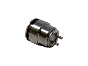
- A 3 mm diameter, piezoelectric based vibration sensor based on the HotSense™ acoustic sensing platform was designed and manufactured, with micro-coaxial cabling to allow positioning within 0.5 mm of rotating gear teeth and allow continuous operation up to 200 °C.
- Piezoelectric sensors are electromechanical transducers, that are immune to magnetic effects to provide a stable and reliable analogue signal in relation to pressure waves from the gear teeth without the need for input power.
- An analogue signal capable of replacing a VR Sensor was created using a high-performance filter and then digitised using ICE Electronics dual channel digitiser up to 50 kHz.

Execution
- The solution was successfully deployed on to an engine platform and sensing achieved whilst operating.
- Additionally, the sensitivity of the solution was able to determine the speed and position of a number of gear teeth, as well as identify missing teeth or teeth showing significant wear damage.
An electrical trace from the sensor
Key Deliverables
- High-fidelity speed and position now enables the customer to access signals other technologies could not. This has allowed them to further optimise engine performance.
- Wear or damage to the gear-train can be effectively realised to make informed decisions on repair and replacement, optimising maintenance costs and planning.
- The sensing solution allowed operation at elevated temperatures, in the presence of magnetic fields for performance in extreme environments.

